The requirements for the switch are discussed. The hardware interfaces are described in detail, and the software function is described in the form of a user's manual. Finally, the hardware and software implementation is presented.
It is concluded that though low-cost, the hardware design is excessively complex. It is found that the simple 3-wire serial interface is sufficient for most applications, and that an RS-232 "break" signal is ideal for obtaining the switch processor's attention. It is seen that a clock/calendar capability could be added at zero cost to the switch design.
It is recommended that an improved switching network design be investigated, that the software functionality be enhanced to allow better security, and that CMOS integrated circuits be used to reduce heat dissipation.
It was decided that requesting the switch's attention should be done via the serial data line. The only serial activity which the switch can monitor on all lines simultaneously is a break signal. This was used. The length of the break signal required was made configurable, so if it is possible to produce variable length break signals, short ones can be sent without dropping into command mode.
A considerable amount of hardware was needed to build a six port version of the switch. Thirty-four IC packages were needed. Implementing the remaining eight ports would require another twenty-six IC packages.
Due to the requirements for the switch processor, it was possible to implement a real time clock/calendar at zero hardware cost. Since the switch will be powered up at all times, this will be a useful feature.
A more elegant solution to the switching network problem should be investigated. At present, the network would require 23 integrated circuits to implement fully, whereas a more sophisticated version using crosspoint switches might only require 5. However, an inexpensive source of the crosspoint switches would have to be found.
Finally, it is recommended that lower power versions of the CPU and EPROM be used. These are available at higher cost, but would reduce heat dissipation.
A property of this type of connection is that it needs to be modified often. Unfortunately, serial port connectors tend to be located on the least accessible portion of any piece of equipment, not all cables work with all equipment, and sometimes it is risky to switch cables while equipment is powered up.
To solve these problems, a fully automatic RS-232 data switch was developed. The switch has well-defined interfaces of both DCE and DTE types, which will connect to virtually any serial port using standard cables. Once the cables are in place, they need not be moved again. The switch is fully intelligent and can be controlled from any of its ports. As well, it provides functions not possible with serial cables, such as dial-in access from the modem to any serial device connected, time and date, and unusual connections such as broadcast and ring capabilities.
In this report, the requirements for this switch are gathered, and a complete implementation is presented. It will be seen that the design is optimized for personal use, and low cost of production in small quantities. A software user's manual is included.
The number of ports should be in line with this requirement. The architecture must support on the order of 10 ports, but beyond this, cost dictates what the maximum will be.
Security provisions should be minimal, but must be sufficient to allow a dial-in modem, or publicly accessible terminal, to be connected to the switch without giving it full access. This necessitates different levels of access, and passwords to switch between them. The switch should be a standalone device. It should not rely on the resources of any devices attached to it, that is, it should have its own intelligence, and a dumb terminal should be enough to control it. The switch will be considered part of the behind-the-scenes wiring between equipment, rather than part of the equipment itself. As such, it needs no switches, lights, or any other I/O devices other than the data ports. It will be powered up all the time, so it needs no nonvolatile memory of any kind. In the event of a power failure, the switch configuration will simply be reloaded by sending a file of commands from an attached computer.
The main goal of the switch is to connect asynchronous serial data, that is, to route the TxD and RxD signals between the ports. It will not be feasible to deal with the remaining signals, but the well-defined outputs should be tied to the appropriate logic levels when not otherwise controlled, to provide valid interfaces.
Beyond the TxD and RxD lines, it is desirable to have an additional input and output line on a port. It is then possible to pass the input through to the output at the other end of the connection, and thus route DTR and carrier detect signals as well as data. Since the DTR input from a terminal and the carrier detect output from a modem both indicate that the equipment is on and communicating, the status of these inputs can be used by the switch software to provide some intelligent features.
Since the switch and most of its peripherals will be located in a single room, providing robust data interfaces is not a problem. Standard RS-232 ports will suffice, with no major concern placed on noise immunity and such factors. It is up to the user to provide current loop converters and whatever else necessary if a terminal does have to be located remotely.
Since the RS-232 interfaces provided by the switch are simple and generic, an equally simple and generic method is needed to obtain the attention of the switch when a port wishes to send it a command. The choice is between signaling in-band using the RS-232 data lines, or out-of-band using an extra input or the DTR line. In-band signaling is preferred, since it allows even terminals with three wire interfaces, and users connected via a modem, to get into command mode. Unfortunately, hardware to detect in-band attention signals on all the ports can become very complex. A reasonable compromise seems to be to detect an RS-232 "break" signal as the attention code.
It is obvious from the earlier requirements that a microprocessor is needed to control the switch. This should be a microcontroller of a type making it possible to build an intelligent control core from a few simple parts. Processing power and memory capacity beyond a few kilobytes are not an issue. Ease of software development is an issue because it affects development time, which is a major cost because the switch will not be built in quantity. One software development feature which should exist is the ability to download experimental firmware into the switch and run it without having to program an EPROM. This vastly decreases the turnaround time for debugging, but requires spare RAM on the same order of magnitude as the EPROM for the code, and ability to execute code from the RAM.
The switch should be able to act transparent for equipment and/or users which are unable to deal with it. For example, it should be possible to route an incoming call on a dial-in modem to another port without intervention from the caller. An automatic connection feature will be provided, so that the modem port can be configured to connect to another port automatically as soon as its carrier detect input becomes asserted.
Finally, it is judged desirable that the switch maintain the time and date. Since it runs continuously and its processor needs to maintain timers anyway, this comes at the cost of only a small amount of software. But it allows computers which have no battery backed-up clocks to query the switch for the time and date at startup.
   ------------------------------------------------------
   \ 13  12  11  10  09  08  07  06  05  04  03  02  01 /
    \                                                  /
     \ 25  24  23  22  21  20  19  18  17  16  15  14 /
      ------------------------------------------------

   Figure 1.  RS-232 Connector Pinout.
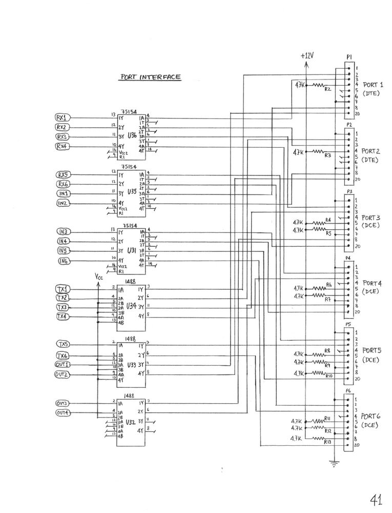
The pins are used as shown in the following table. Pins which are not listed are not connected on any port. Pins which are shown as "+12V" are tied high via a 4.7 K Ohm resistor to prevent damage if the wrong type of equipment is plugged in.
   Pin  Name   DTE 1-2      DCE 3-4      DCE 5-6

    1   FGND   Ground       Ground       Ground
    2   TxD    Data out     Data in      Data in
    3   RxD    Data in      Data out     Data out
    4   RTS    +12V         N.C.         N.C.
    5   CTS    N.C.         +12V         +12V
    6   DSR    N.C.         +12V         +12V
    7   SGND   Ground       Ground       Ground
    8   DCD    Aux. input   Aux. output  N.C.
   20   DTR    Aux. output  Aux. input   Aux. input
The "Data out" and "Aux. output" lines are driven by standard MC1488 line drivers. This means that they are current-limited to 10 mA and can withstand a short circuit to any voltage between -12V and +12V. In particular, this means that there will be no damage from incorrect cabling.The "Data in" and "Aux. input" lines are monitored by DS75154 line receivers with the threshold control terminals open. This means that the positive going threshold is at 2.2V, and the negative going threshold is at 1.4V. Therefore, noise spikes of less than 0.8V will not affect the system, and ports whose peripherals are powered down or disconnected (0V at all inputs) are considered to be in the RS-232 "idle" state, and as having DTR deasserted. This is a desirable property.
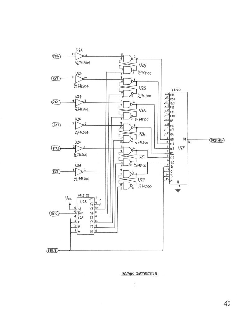
An RS-232 "break" signal is used to obtain the processor's attention. This signal consists of the RS-232 line being continually high (+12V, logical zero) for a period exceeding a normal character time. While break signals are passed through the switch, they are monitored, and if the length of a break exceeds a threshold, it is considered a request to enter command mode. The threshold is programmable for each port, in icrements of 10 milliseconds.
Since the switch is completely asynchronous, when a port is connected to another port, serial data is passed through the switch in a few tens of nanoseconds. However, when DTR or carrier detect is passed through between ports, this is handled by the microprocessor on a 10 millisecond polling cycle. This means that these signals can be delayed up to 10 milliseconds, making them unsuitable for time-critical applications such as hardware handshake. They are updated quickly enough for their intended purpose as carrier detect and terminal ready indicators, however.
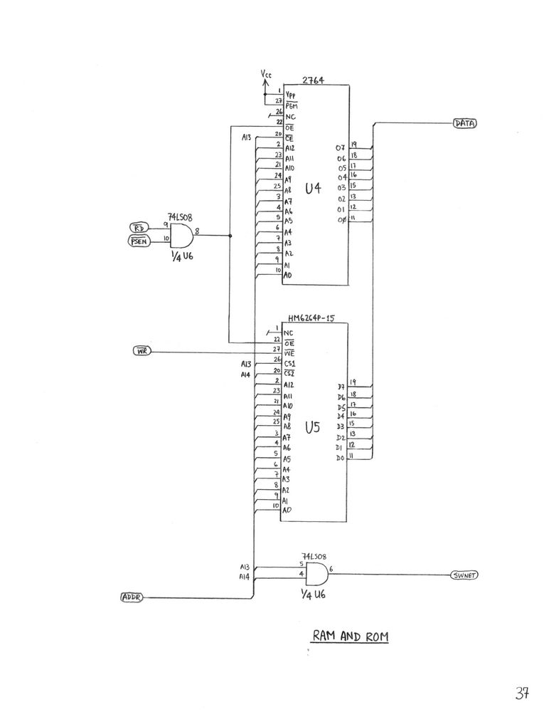
Address decoding is done by connecting A13 and A14 to the CS1 and CS2* inputs of the RAM, and A13 to the CE* input of the EPROM. A13 and A14 are combined in an AND gate to generate the enable signal for the switching network. This results in the following memory map:
     Address Range     Function

     $0000 - $1FFF     EPROM
     $2000 - $3FFF     RAM
     $4000 - $5FFF     Shadow of $0000-$1FFF
     $6000 - $7FFF     Switching network
     $8000 - $FFFF     Shadows of $0000-$7FFF
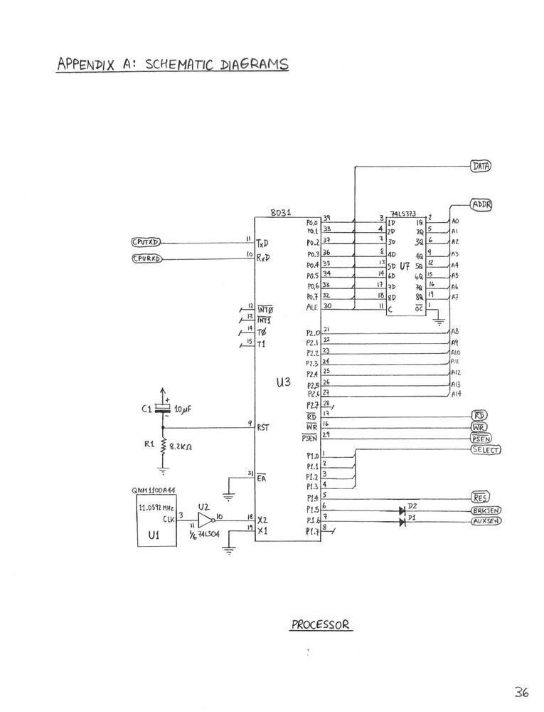
The processor WE* signal is fed directly to the RAM, but the RD* and PSEN* signals are combined using an AND gate before being used to enable both the EPROM and the RAM. This means that the machine can see the entire memory map in both code and data space. This allows some code space instructions to be used for data manipulation, and code to be executed from RAM. This, combined with the fact that the RAM is sufficiently large, was used during software development to debug software loads in RAM.Two diodes are shown on input lines going to the processor. This is a failsafe, since the processor port lines are bidirectional and these two are driven by an external source. A programming error cannot do damage this way, since the processor output drivers are open-collector.
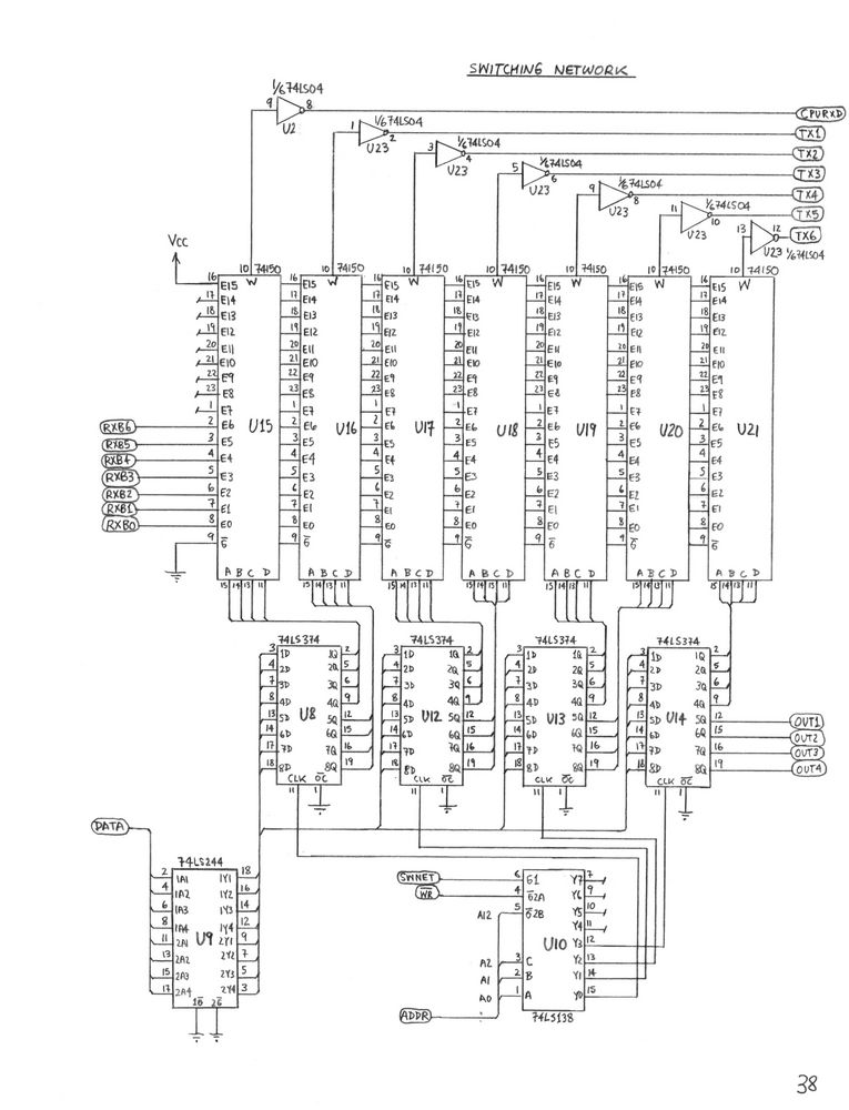
The switching matrix is at the top of the page. It consists of 74150 data selectors. These are not the most elegant method of implementing a switching network, but they are cheaply and commonly available, which more sophisticated switching network construction blocks (e.g. crosspoint switches) are not.
Each data selector obtains 4 bits of selection information from the processor interface section, for the following memory map:
     Selector   Port   Address   Bits

       U15      CPU     $6000    0-3
       U16       1      $6000    4-7
       U17       2      $6001    0-3
       U18       3      $6001    4-7
       U19       4      $6002    0-3
       U20       5      $6002    4-7
       U21       6      $6003    0-3
The top 4 bits of the register at $6003 are used for the auxiliary (DCD/DTR) outputs on the first four serial ports. If the system is expanded in the future, the top 4 bits of the last installed register will be used for this purpose instead.
Page 39 shows the data selector used to scan the auxiliary (DTR/DCD) inputs. It is also driven by the SEL lines from the processor, but first they are buffered to be able to drive two standard TTL loads. The buffering of the serial data lines is shown on the same page.
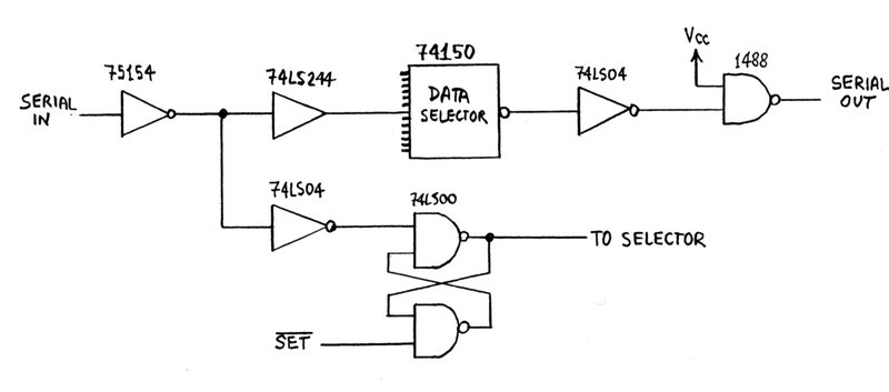
Figure 2. Serial Data Path.First, the RS-233 voltage levels are converted to TTL by a DS75154 line receiver. At this point, the idle state of the lines is high. This is buffered by a bus driver (74LS244) of sufficient capacity to drive 15 standard TTL inputs, and sent to the bank of data selectors.
The data selectors invert the logic level, so that its idle state is now low. A 74LS04 inverts it again, and then a MC1488 line driver drives the RS-232 port output.
It can be seen that both the 74LS04 inverters could have been saved by using an inverting bus driver and taking the RESET* signal for the R-S latch from its output. Unfortunately, this would have meant that the idle logic level at the 74150 input is low. This, in turn, would have meant that in a fully configured, idle system, 15 x 16 = 240 standard TTL inputs would have been drawing current. Since the 74150's are not available in low-power versions, this would have meant about 1.5 watts of power wasted. To eliminate the waste, the extra inverters were used.
Line Input Buffer

     buffer:    array[81] of char
     pointer:   byte
This is where the command line typed by the user is stored. 80 bytes are reserved for the command line, plus one for the terminating zero. The pointer is set to the beginning of the buffer when the line is received, and incremented when processing characters until it reaches the terminating zero.
Port Name Table

     array[6,9] of char
The port names assigned by the "NAME" command are stored here. Each entry has the following structure:
Baud Rate Table

     array[6,7] of byte
This structure stores the baud rates in most-recently-used order for each of the 6 ports. The baud rates are encoded as numbers from 1 (110 bps) to 7 (19200 pbs), and ordered such that the first one is the most recently used one.
Connection Tables

     physical:  array[8] of byte
     logical:   array[6] of byte
     owner:     array[6] of byte
The physical connection table is simply a shadow image of the values loaded into the connection registers, since these are write-only. In addition to the input selects for 6 ports, its stores the input select for the CPU, and the state of the 4 auxiliary outputs, which are in the highest connection register.The logical connection table stores the number of the port each port is listening to, or 15 if the port is receiving silence. The logical connection table does not always mirror the physical table, since connections have to be suspended when a user enters command mode. The connection owner table stores which port established each connection.
Break Detection Tables

     timeouts:  array[6] of byte
     counters:  array[6] of byte
     flags:     array[6] of byte
The break timeout table stores the break timeout for each port in increments of 10 milliseconds. A zero in any entry means that breaks for that port are to be ignored. The break counter table is used to keep track of the length of breaks. A zero in a counter means that no break is in progress, a positive value means that a break is in progress but not sufficiently long yet, and a -1 means that the break is long enough. The flags are used to signal break events. They are set to non-zero when a break occurs, and reset to zero when it is processed.
Auxiliary Input Scan Tables

     timeouts:  array[6] of byte
     counters:  array[6] of byte
     flags:     array[6] of byte
The auxiliary input timeout table stores the timeout for each DCD/DTR input in units of 1 second. A zero in an entry means that the auxiliary input of the corresponding port should be ignored. The counters are used to keep track of how long an input has been deasserted. A zero in a counter means that the input is asserted, a positive value means that it has become deasserted but not timed out yet, and -1 means that it has become deasserted and timed out. The flags are used to signal the following:
     0: No event
     1: DTR/DCD has become asserted
     2: DTR/DCD has been deasserted for the timeout interval


Attention Flag

     boolean
This flag is set by the interrupt service routine when it has modified the break or auxiliary input flag tables. The mainline code checks this flag periodically, and services events when it becomes set. It then clears it again.
Break Queue and Flag

     queue:     array[7] of byte
     flag:      boolean
The break queue indicates which ports have sent a break and are waiting for service. Normally, the queue is empty, which is indicated by a single zero in its first location, and the flag clear. When the queue is not empty, the flag is set, and the waiting port numbers are in the queue in least-recent order. A zero marks the end of the queue. There is enough space for all ports to be in the queue.
Auxiliary Output Data

     defaults:  array[4] of byte
     mask:      bit-field
These variables indicate how the auxiliary output line on ports 1-4 should be handled. In the mask, there is one bit for each port. The bit is set if the port should receive the auxiliary input status of the port it is connected to, or clear if the output should always be asserted. The table of defaults indicates what the outputs should be when the port is not connected to anything. Each entry can be 0 or 1, for deasserted and asserted, respectively.
Passwords

     restrict:  array[9] of char
     maint:     array[9] of char
These are the passwords used to get out of restricted, and into maintenance mode, respectively. Each is an ASCII string of maximum 8 characters, terminated with a zero. The strings may be null if passwords are not used.
Restriction Tables

     flags:     array[6] of byte
     mask:      array[6] of 16-bit-field
The flag array stores whether each port should be in restricted mode when it enters command mode. A zero in an entry indicates no restriction, any other value indicates restriction. The mask array consists of a 16-bit field for each port, of which only the low 6 bits are currently used. The value entered by the "MASK" command is stored here.
Autoconnect Table

     array[6] of byte
This table stores the autoconnect information for each port. A zero indicates that no autoconnect has been set, a nonzero value indicates that the given port should be autoconnected to.
Time/Date Structures

     clock:     array[6] of byte
     shadow:    array[6] of byte
     get-flag:  boolean
     set-flag:  boolean
The clock structure stores the current time and date, in this order: Hour, minute, second, day, month, year. The year is stored as a number between 0 and 99, corresponding to the interval between 1980 and 2079. The values in the clock structure are updated by the interrupt routine.The shadow structure is accessed by the mainline code. It sets the get-flag to request that the time be copied into the shadow registers, or the set-flag to request that the shadow registers should be used to set the time. Then it waits for the interrupt routine to clear the flag to indicate that the operation is complete.
Interrupt Prescale Counters

     counter1:  byte
     counter2:  byte
Counter 1 is preset at 36, and decremented 3600 times per second at the main interrupt entry point. When it reaches zero, it is reloaded and the 10 millisecond interrupt processing is done.Counter 2 is preset at 100, and decremented 100 times per second at the end of the 10 millisecond processing. When it reaches zero, it is reloaded and the 1-second interrupt processing is done.
Software Timers

     idletim:   byte
     limittim:  byte
Both timers can be loaded with a nonzero value by the main program, and will then be decremented once per second by the interrupt routine. When they reach zero, they are not decremented further. These timers are used to implement the 30-second timeouts used to force users out of command mode when others are waiting.
Access Level Flags

     restrict_flag:  boolean
     maint_flag:     boolean
These flags are used to encode the current access level. When both are zero, the access level is normal. When the restrict flag is set, the access level is restricted. When the maint flag is set, the access level is maintenance. The flags are mutually exclusive.
Once every 10 milliseconds, the interrupt routine does not return, but reloads the counter. It then reenables the interrupt, because the processing it is about to perform uses more than 256 instruction cycles and needs to be interruptable when the timer runs out again.
First, the scan for breaks is done, and the data tables relating to break detection updated. Next, the auxiliary (DCD/DTR) outputs of ports 1-4 are serviced, by fetching the auxiliary input status of any port they are connected to and loading it into the outputs. Finally, the time and date are copied from the main counter registers into a temporary location, or vice versa, if this was requested by the main program. The main program does not access these directly to avoid race conditions. Then, a second counter is used to return from the interrupt routine unless a full second has expired.
Once per second, the interrupt routine continues by updating the time and date. It also scans the auxiliary inputs for changes of state, and maintains the timers and data tables related to them. Finally, it maintains two timers, decremented once per second, which are used to time out a user when another user is waiting.
In the test implementation, it was found that the microprocessor was a major source of heat. A CMOS version of the processor would generate much less heat, and the wiring of only two pins (the clock inputs) would have to be modified to accommodate it. As well, a CMOS EPROM could be used. This is significant, since the equipment will be powerd up all the time, and may not be located where there is adequate ventilation.
Practical experience will show how useful it is to have the auxiliary (DCD/DTR) outputs on ports 1 to 4. If they are very useful, it may be worth the effort to implement auxiliary outputs on all ports. Address decoding and an extra register would have to be added, however.
The switch is controlled by entering commands. Any one port can be in command mode at a time. The RS-232 "break" signal is used on a port to request command mode. Requests are queued and served in turns if the switch is busy.
Connections are established by selecting a "source" port for each port to obtain its data from. When two ports are selected to have each other as source ports, a bidirectional connection is set up. Other types of connections, such as broadcasting to more than one port, or a ring configuration, can also be set up.
Security is provided in the switch software by having three access levels. In the lowest access level, only a basic command set is accessible, and only a specified set of ports may be connected to. In the highest level, all switch commands, including configuration commands, are available. Passwords are required to switch between access levels. There is sufficient security to permit a dial-in modem to be connected to the switch.
To configure the switch, press the "break" key on the terminal. This must generate an RS-232 break of at least 100 milliseconds to be recognized. The prompt
<RETURN>will be sent to the terminal at 1200 bits per second when the switch recognizes the break. Press the RETURN key on the terminal at this point. If you wish to use a baud rate other than 9600, press RETURN repeatedly until the prompt appears at the correct baud rate, then press RETURN one more time.
A sign-on message is printed on the terminal, followed by prompts for the restricted mode and maintenance passwords. These passwords are required to get out of restricted mode, and into maintenance mode, respectively. Null passwords may be entered if security is not desired.
When the passwords have been entered, the switch will enter command mode and display its ">" prompt. The access level will be set to maintenance, and all other ports will be enabled to request command mode.
The user's view of connections follows this principle. Each port has a "source" port associated with it, from which it obtains its data. Normally, two ports have each other selected as sources to establish a bidirectional connection, but this is not a requirement. A port can be disconnected by setting it to listen to the "silence" input of its data selector. In the user's view, such a port is disconnected.
When a port enters command mode, it communicates with the switch microprocessor. During this time, all connections involving this port are suspended, and ports normally listening to it receive silence. When the port exits command mode, the connections are reestablished.
<RETURN>on the requesting terminal. This allows the correct baud rate to be selected. The user must press RETURN until the command prompt appears. The "
1200, 2400, 4800, 9600, 19200, 300, 110When the correct baud rate has been found, this list is rearranged so move this entry to the front. So for example, if a port has just entered command mode at 9600 baud, the list will now be as follows:
9600, 1200, 2400, 4800, 19200, 300, 110A separate list is kept for each port, and the lists are kept in most-recently-used order. This allows for quick and painless baud rate detection.
When the baud rate has been established, the switch command prompt, consisting of a ">", is displayed. At this point the switch command set, described in the next section, is available. A summary of all possible command syntaxes can be obtained by typing "HELP" or just "?".
While entering a command, the special characters DEL, backspace, and CTRL-X are recognized. The first two are used to delete one character, and CTRL-X is used to delete the entire line.
To exit from command mode, the "BYE" command is used. This returns the port to the state it was in before the break signal was sent.
When this happens, the requesting port is put into a queue. Any other ports requesting command mode will also be enqueued. All ports except the one in command mode can be on the queue at the same time. Repeated break requests from a port which is already in the queue are ignored.
When others are waiting, a port may only be in command mode for 30 seconds. The time remaining is indicated before each command prompt. For example, the prompt
09>means that 9 more seconds are allowed. When the time expires, the port is forced from command mode and the first request on the queue is serviced.
Additionally, an idle timer is maintained, which counts the time since the last keystroke. When this timer reaches 30 seconds and another user is waiting, the session is aborted, regardless of the time remaining. Thus, if a port has been in command mode and idle for some time, and another break request comes in, the command session is aborted immediately and the break serviced.
When a port initially enters command mode, it will be in normal or restricted mode, as selected by the "MODE" command. If it is in restricted mode, the message
RESTRICTED MODEis printed just before the first prompt. At this point, the access level can be switched using the "RESTRICT", "NORMAL", and "MAINT" commands. Passwords are required to switch to a higher access level.
The inputs and outputs are meant to be analogous to the "on hook" and "off hook" status of a telephone. That is, when the auxiliary input is deasserted, it is interpreted as the device connected to that port having been turned off, and auxiliary outputs can be controlled to indicate whether their port is connected to something. The details of this are described, with real-life examples, in the command section.
The arguments to each command are shown in angle brackets, such as <arg>. Optional arguments are shown in square brackets, such as [<optional>]. Alternate command syntaxes are shown on separate lines.
Most arguments are decimal numbers or string tokens. Decimal numbers must be positive integers ranging from 0 to 255. String tokens can be abbreviated like commands, and their shortest possible abbreviations are shown similarly.
Wherever it is required to enter a port identifier, this can be the port number (1 to 6), or the name assigned to that port.
BAUD Syntax: BAudDescription: This command sets the baud rate to be used on a given port. The baud rate can be one of the following: 110, 300, 1200, 2400, 4800, 9600, or 19200. If the port number is that of the controlling port or ommitted, the baud rate is set immediately, and it is necessary to switch the terminal to that baud rate in order to continue entering commands. If the number is that of another port, the specified baud rate is moved to the front of the queue, so it will be tried first when that port enters command mode.[<port>]
It should be noted that baud rates can be abbreviated like any other part of a command, thus "1" will specify 110 baud, "12" will specify 1200, and so forth.
BYE

Syntax: Bye
Description: This command causes the controlling port to exit from command mode. All connections which are currently suspended because they involve the controlling port are restored.
CALL

Syntax: Call <port>
Description: This command establishes a bidirectional connection and immediately exits from command mode. For example, if port 5 has just entered command mode and issues the command "CALL 3", port 3 is set to listen to port 5, port 5 is set to listen to port 3, and port 5 exits from command mode so that it is immediately connected to port 3.
To prevent interference, this command will first remove any connections involving the controlling port as the source. So for example, if port 1 and 2 were listening to port 5 when it issued the above command, these connections will be cleared. This is done so that successive CALL commands to different destinations do not interfere with each other - each will remove the connections set up by the previous one.
The destination port must be available. This means that it must not be involved in a connection belonging to another port. If it is already involved in a connection belonging to the controlling port, the connection is simply overwritten.
CLEAR

Syntax: CLear
Description: This command clears all the connections belonging to the controlling port.
DATE

Syntax: Date
Description: In normal or restricted mode, this command prints out the current time and date. This is printed in the following format:
YYYY/MM/DD HH:MM:SS
The format was chosen to be easily readable by computer as well as human, so computers without real-time clocks can issue a break, get into command mode, and retrieve the date automatically.
HELP

Syntax: Help
        ?
Description:
This command prints out a summary of the syntax of all available commands. Maintenance commands are only listed if the controlling port is in maintenance mode.
LINK

Syntax: LINk <dest port> <source port>
Description: This command establishes a link between two ports. The port specified by <dest port> is selected to listen to the port specified by <source port>. This command is not available in restricted mode.
When a connection is established, the "owner" of the connection is recorded as the controlling port.
A connection cannot be established if the destination port is already involved in a connection belonging to another port. It is possible to listen to connections belonging to other ports, however. An existing connection involving the destination port is simply overwritten if it belongs to the controlling port.
LIST

Syntax: List
Description: This command lists all the current status information of the data switch. One line of data is presented for each port, with the following columns:
  P#   - Port number.
  NAME - Port name as assigned by the "NAME" command.
         The port may be referred to by number or name.
         The name is prefixed with "*" if this is the
         current controlling port, or "-" if it is the
         first port in the queue waiting for command mode.
  BAUD - The most recently used baud rate for this port,
         i.e. the value at the head of the baud rate list.
  CONN - The port which this port is listening to,
         or "-" if the port is unconnected (listening to silence).
  OWN  - The owner of the connection, or blank if no connection.
  BRK  - The break timeout (in multiples of 10 milliseconds)
         for this port, or "-" if breaks are ignored.
  DCD  - The setting of the auxiliary output (DCD for terminal
         ports, DTR for modem ports).  The first entry is "S"
         if the output is copied from the corresponding input
         at the port connected to, or "1" if the output is
         forced true at all times.  The second entry is the
         default setting when the mode is "S" and the port is
         not connected.  This entry is blank if the port
         does not have a controllable auxiliary output.
  DTR  - The status of the auxiliary input (DTR for terminal
         ports, DCD for modem ports).  The first entry is the
         timeout (in seconds), or "-" if the input is being ignored.
         The second entry is the actual state of the input.
  REST - Access restriction for this port.  If blank, no
         access restriction is in effect.  If an "R" is shown,
         the port will always be in restricted mode when it
         enters command mode.  The next two digits are the access
         mask, in hexadecimal, as set by the "MASK" command.
  AUTO - Which port this port should autoconnect to when its
         auxiliary (DTR/DCD) input becomes asserted.  Blank if none.


OFF

Syntax: Off
Description:
This command clears all connections belonging to the controlling port, and drops out of command mode. It is identical to a "CLEAR", followed by a "BYE". It is intended for use by ports whose DTR/DCD input is being ignored, and whose connections are therefore not cleared automatically.
UNLINK

Syntax: Unlink <port>
Description: This command clears a connection by setting the selected port to listen to silence. The connection must belong to the controlling port, unless it is in maintenance mode.
Example: Assume port 2 has just made a call to port 4 and wishes to clear the connection manually. The two following commands will do the job:
	UNLINK 2
	UNLINK 4
MAINT

Syntax: Maint
Description: This command places the controlling port in maintenance mode. If it is not already in maintenance mode, the correct maintenance password must be entered when prompted for.
NORMAL

Syntax: Normal
Description: This command places the controlling port in normal mode. If it is currently in restricted mode, the correct restricted mode escape password must be entered when prompted for.
RESTRICT

Syntax: Restrict
Description: This command places the controlling port in restricted mode, regardless of its previous access level.
AUTOCONNECT

Syntax: Autoconnect Off [<port>]
        Autoconnect <dest port> [<port>]
Description:
An autoconnection occurs when a port's auxiliary input changes from deasserted to asserted, the input is not being ignored, and a port has been specified to autoconnect to. If all these conditions are met, then an automatic "CALL" is done to the selected port without command mode being invoked (and while another user may be in command mode). Since connections are also automatically cleared when the auxiliary input is deasserted again, this can make the switch completely transparent to the autoconnecting port.An autoconnect is not processed if either end of the requested link is already in use.
This command controls autoconnects. The first argument must be "Off" for (no autoconnect), or a valid port to connect to. The second argument specifies the target of the command. If not given, the autoconnect status of the current control port is changed.
BREAK

Syntax: BReak Timeout <time> [<port>]
        BReak Ignore [<port>]
Description:
This command specifies how long an RS-232 "break" signal must be before it gets the attention of the switch. The allowed values are from 1 (10 ms) to 255 (2.55 seconds). In all cases, a break signal 10 ms longer than the indicated interval is guaranteed to be recognized.If a very small timeout is set, then certain characters at 110 bits per second may trigger false break detections. The solution is to increase the timeout. If the timeout is set to "ignore", then breaks on a port are ignored completely, and the port can not enter command mode.
The last argument is the port number for which the command is; if this is not specified, the current control port is affected.
DATE

Syntax: Date <YY/MM/DD HH:MM:SS>
Description: This is the maintenance version of the date command. In maintenance mode, it takes an optional argument consisting of a date formatted as shown. If the date is valid, it is loaded into the internal clock. The clock only remains valid until the next time the switch is powered down.
If the "YY" digits are 80-99, they are interpreted as year 1980-1999. But if they are 00-79, they are interpreted as year 2000-2079. This should be sufficient for the expected lifetime of this data switch.
DCD

Syntax: DCd Default <0|1> [<port>]
        DCd Force [<port>]
        DCd Source [<port>]
Description:
This command controls the auxiliary (DCD/DTR) output for the specified port. If the port is not specified, the current control port is affected.The mode must be either "Source" or "Force". The former copies the output from the corresponding input of the port connected to. The latter forces it to true at all times. The "Default" subcommand allows the default value of the output to be set to 0 (deasserted) or 1 (asserted). This value appears when the mode is "Source", but no port is connected to.
Finally, when the mode is "Source", but a port is connected to whose auxiliary input (see "DTR" command) is ignored, then the output will be asserted unconditionally.
Examples: Port 1 is connected to a modem. The modem should have DTR asserted when not in use, so it can autoanswer. But when connected, it should get DTR from the other end of the connection, so the modem can be forced to hang up the line by dropping DTR (many terminal and bulletin board system programs expect this). The settings are therefore:
	DCD DEFAULT 1 1
	DCD SOURCE 1
Now assume port 3 is connected to a computer running a host program. The computer should get carrier detect only when something is actually connected to it.
	DCD DEFAULT 0 3
	DCD SOURCE 3
Finally, assume that port 4 is connected to a machine which refuses to send unless it always sees carrier detect.
	DCD FORCE 4


DTR

Syntax: DTr Ignore [<port>]
        DTr Timeout <time> [<port>]
Description:
This command specifies how the auxiliary input (DTR for a terminal port, DCD for a modem port) should be handled for the given port. If no port is given, the current control port is assumed.When the setting is "Ignore", the input is ignored unconditionally. No autoconnects or automatic disconnects are done, and when the port is connected, if the other end has "DCD SOURCE" in effect, it always sees the input as asserted.
When the setting is "Timeout", a timeout from 1 to 255 seconds can be set. When the DTR input is deasserted for that number of seconds, all connections for the port are cleared and it is dropped from command mode (i.e. the equivalent of an "OFF" command is done). When the DTR input is asserted after having been deasserted for the time indicated, autoconnect processing is done.
Examples: Assume port 1 is connected to a dial-in modem. When the modem asserts carrier detect and no other port owns a connection to it (i.e. when it answers a call by itself), it should autoconnect to another port. When the carrier disappears, the connection should be cleared instantly. Thus we set "DTR TIMEOUT 1 1".
Assume port 3 is connected to a host computer running a communications program which permits hanging up a modem by briefly deasserting DTR. We thus set "DTR TIMEOUT 5 3", indicating that a loss of DTR up to 5 seconds should be ignored. If the computer is turned off, however, the timeout will elapse, and its switch connections will be cleared.
Assume port 5 is connected to a terminal with a cable which does not pass DTR. We thus set "DTR IGNORE 5".
MASK

Syntax: MASk <mask> [<port>]
Description: This command sets the set of ports which a port can access in restricted mode. The second parameter is optional and specifies which port the mask should be set for. If it is not given, the current control port's mask is changed.
The "mask" parameter is a 1-4 digit hexadecimal number containing a bit mask. Bit 0 corresponds to port 1, bit 1 corresponds to port 2, up to bit 5, which specifies port 6 (the current maximum).
Example: Assume port 1 is the modem again. An incoming call on the modem should only have access to ports 1 (permitting loopback testing), 3, and 6. This corresponds to the binary number 100101, or 25 hexadecimal. We therefore do "MASK 25 1".
MODE

Syntax: MOde Normal [<port>]
        MOde Restrict [<port>]
Description:
This command sets the default access level for a given port. This can be normal or restricted mode. It is set every time the port enters command mode. If no port is specified, the current control port is assumed.
NAME

Syntax: NAme <port> [<new name>]
Description: This command displays or sets the name for the given port. The name is set if given, otherwise it is displayed. A name can have up to 8 characters, no spaces, and any lowercase letters are converted to uppercase. A port can be referred to by name as well as number. The default port names are "P1" through "P6".
Names can be abbreviated. This can lead to conflicts. For example, if a 68000 development system is on port 5, and port 5 is named "68000", then a "CALL 6" command will be diverted to port 5, since "6" is an abbreviation of "68000" as well as a number. It is therefore suggested that names beginning with a digit from 1 to 6 should not be used.
Port 1: An intelligent (Hayes-compatible) modem in autoanswer
        mode, providing carrier detect, and not ignoring DTR.
        The modem only autoanswers when DTR is asserted, and
        immediately drops calls when DTR becomes deasserted.

Port 3: A computer running a bulletin board system program.
        The program sees an incoming call when its carrier
        detect input is asserted, and drops unwanted calls
        by briefly deasserting DTR.

Port 5: A dumb terminal with DTR connected.

Port 6: A dumb terminal located at some distance from the
        switch, with DTR not connected.
The following capabilities are desired:
Port 1: DTR asserted when not connected to anything (allows autoanswer by the modem). DTR obtained from the other end of a connection once it is established. Carrier detect not ignored, and connections cleared immediately on hangup. Restricted mode by default, access only to port 3, where the BBS is. Autoconnect to port 3. Default baud rate 1200, followed by 2400.
	NAME 1 MODEM
	DCD DEFAULT 1 1
	DCD SOURCE 1
	DTR TIMEOUT 1 1
	MODE RESTRICT 1
	MASK 4 1
	AUTOCONNECT 3 1
	BAUD 2400 1
	BAUD 1200 1
Port 3: Carrier detect only asserted when connected to something providing it. DTR monitored, but with a 5 second timeout.
	NAME 3 BBS
	DTR TIMEOUT 5 3
	DCD DEFAULT 0 3
	DCD SOURCE 3
Port 5: DTR monitored, with shortest possible timeout (the terminal only drops DTR when it is turned off, unlike the computer which drops it to signal the modem).
	NAME 5 TERM1
	DTR TIMEOUT 1 5
Port 6: DTR ignored, fake DTR given to BBS if this port connects to it.
	NAME 6 TERM2
	DTR IGNORE 6