I used to have this dream of a "computerized home" where a benevolent computer, on a piece of plywood on the wall in the basement somewhere, would oversee the lights and heating, turn on radio or TV when interesting shows come on, make voice announcements of important reminders and so on. I would be able to control this wondrous machine with a remote control from anywhere in the house, or call it up on the telephone, or push buttons on a locally wired keypad or whatever.
I started working on this thing during my spare time after work in 1992, a piece at a time, without a firm plan in mind. The main part was the controller board, with the ubiquitous 8031 microcontroller. I hadn't fully realized that the complexity of what I was up to was not a good match for such a simple CPU programmed in assembly language. My 68008 board would have been a better idea, and some sort of surplus PC (at the time this would have been a PC/XT class machine) or even an old Commodore 64 a better one yet.
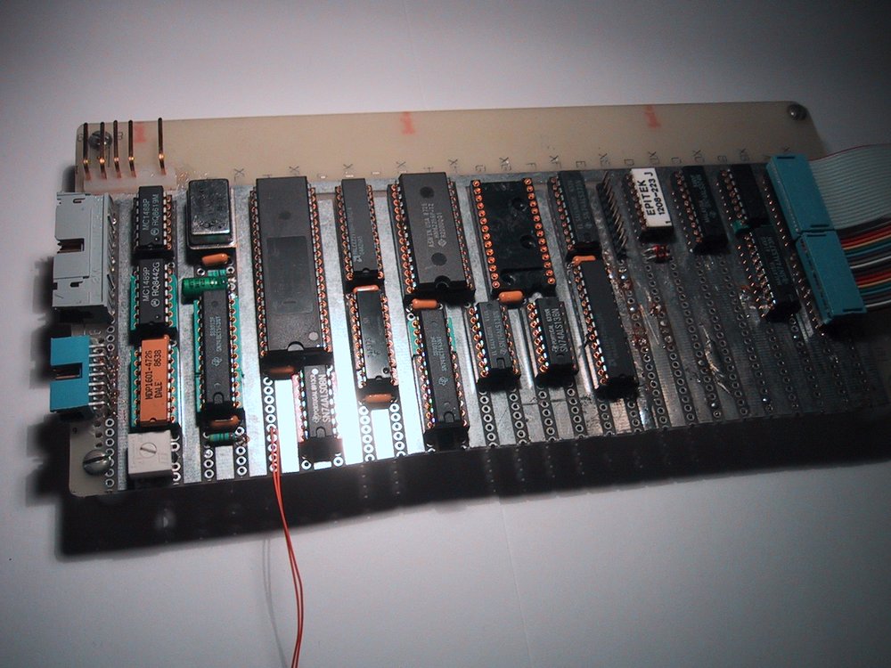
Anyway, here we have the main controller board.
On the left, the power connector, the serial port connector (for a short ribbon cable with a standard DB25 connector on the end) and the connector for the 40 character x 2 line LCD display. About 2/3 across, the connector for the keypad, and on the far right, the connectors for the ribbon cables going off to the other modules.
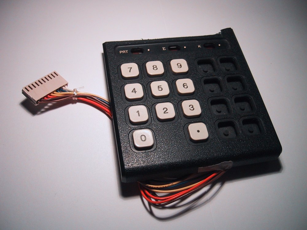
Here are the keypad (salvaged from a calculator; any final version of the system would have used a nicer one of course) and the LCD.

The first order of business, given my interest in telephony (this was before I built my PBX), was a telephone interface, which we have here:
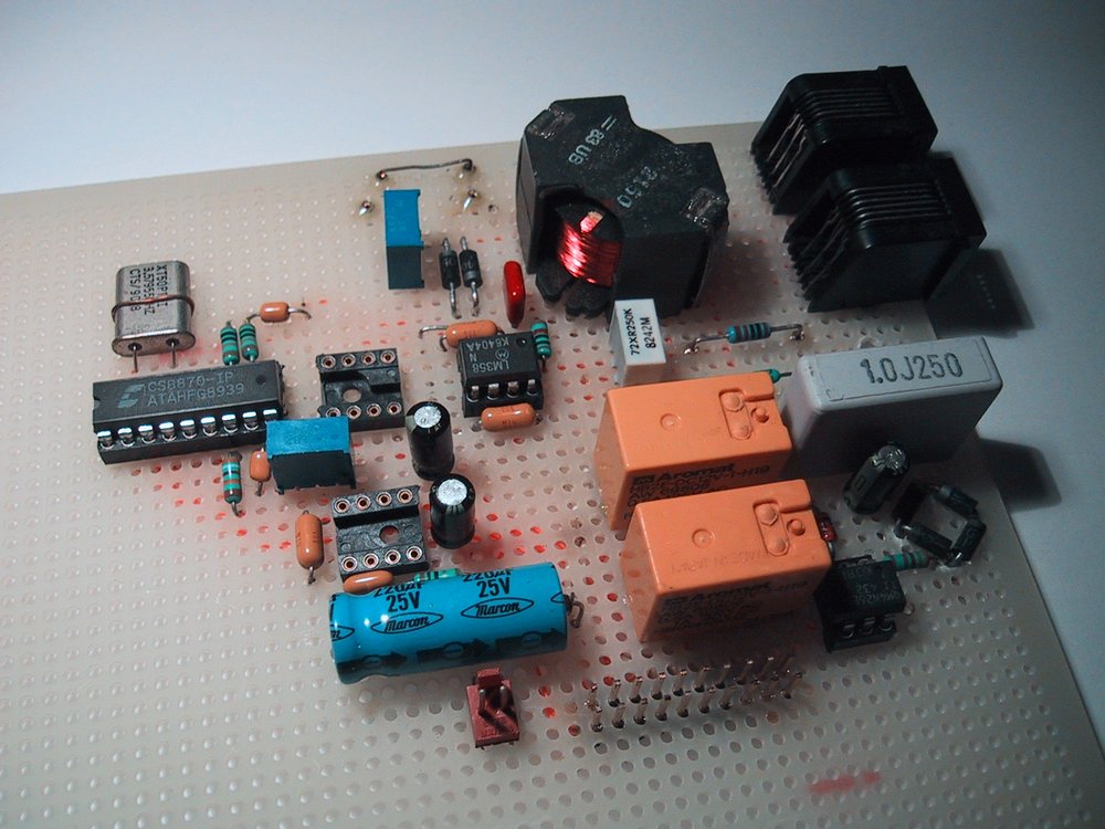
This interface could monitor a telephone line for DTMF tones, with or without actually picking up the phone. The idea was that it would sit in front of an answering machine and let the machine answer, and listen for a DTMF code on the line. If the correct code was heard, it would pick up, disconnect the answering machine, and take over. Of course, it also had a ring detector and autonomous answer capability. The IC on the left is a Crystal Semiconductor 8870 DTMF decoder.
If you're going to answer the phone, it helps if you have something to say. I remembered that Radio Shack used to have voice synthesizer chips, but when I looked in the catalog, they were not there any more, having gone obsolete (as computers were getting more powerful, dedicated voice synthesizer hardware was no longer needed - the Amiga had a perfectly good software voice synthesizer from about 1986). However, a colleague had bought some years before and not used them so he resold them to me. The chips have 1984 date codes. Here is the board, with the text-to-speech IC, the synthesizer IC and the ancillary parts to make them work.
With this added, my system could talk. Right away, this was integrated with the telephone capability. Now, you could phone it up, enter the code, and it would break into the line and say "Hello". Then you could navigate your way through voice menus, with your input being DTMF tones, and the remote end responding by voice.
About that time, I found a couple of identical TV remote controls in the garbage at work. Hey, cool! Remote control capability. I hooked a storage oscilloscope across the LED at work, and plotted out the signals emitted by the remote when various buttons were pushed. The protocol was not hard to figure out. Also, Radio Shack had a $5 module that received infrared remote control signals and output a TTL version of the signal.
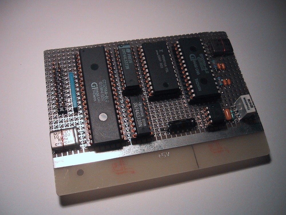
To decode this waveform on the 8031 required all its attention, so I had to build a second CPU board dedicated to remote control operations. Here it is. The two small connectors connect to the IR receiver and transmitter.
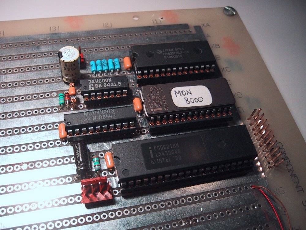
I started working on the firmware for this board. It had a command line interface like the main board (you could remotely login to the infrared board from the terminal connected to the main board) and it could learn remote codes and replay them later under direct command control, or through a communication protocol under command from the main processor. Infrared remote control codes are sent with a 38KHz carrier frequency (that is "on" is a 38KHz flicker, "off" is darkness). The receiver module took care of demodulating this, but to transmit, I had to generate the carrier again, and of course I did this in software.
By the time I was done this part, I had quite a nice standalone learning remote control system. For the transmitter, I initially used an infrared LED that I had bought. But the results were not encouraging: I got a useful range of about 30 centimetres. How could this be, when a normal remote control got fifty times as much? I went back to the oscilloscope. Aha! The real remote control pumped something like 2 amperes of current through its two LEDs. The LEDs could survive this because of the short pulses. At this point, I sacrificed one of the remote controls and sawed off the whole front part of the circuit board, where the LEDs and the driving transistors were, and interfaced that to my board. I made sure to AC couple the enable signal, so a software fault could not leave the LED on for more than a millisecond or so. Otherwise I would have soon burned it out.
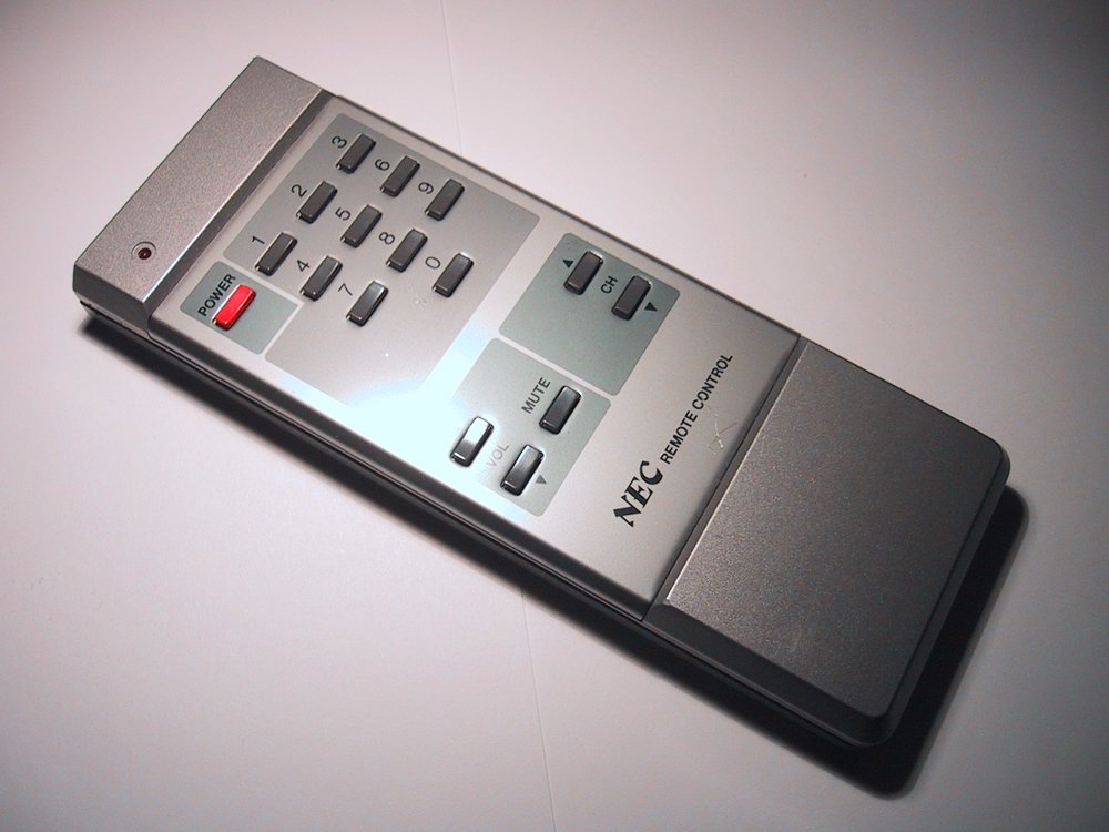
Here is the still intact remote control, and the infrared transmitter.
![]()
That's all the hardware. The only thing missing is the infrared receiver. That's because I needed the receiver module for my jukebox system
I wrote a lot of code for this thing. I started with the command line interface routines that I had written for my data switch. The fancy timer code was later integrated into the data switch, and the infrared remote control code found a home in the jukebox remote pod. In fact, as I went along, I built up quite a library of useful routines. Some snippets of code made it into my PBX too.
But then I got bored with it and never really "finished" it, though all the parts you see worked.
There are no schematics for this stuff, just a few scribbled notes on pieces of paper long ago misplaced. But I still have all the code.
   Main Board

   part1.asm - main code
   part2.asm - lots of utility functions
   part3.asm - timer interrupt and keypad scan
   part4.asm - LCD menu and infrared user interface
   part5.asm - timer code
   part6.asm - telephone interface code
   part7.asm - main event loop

   Infrared Board

   ircode1.asm
   ircode2.asm
Because the assembler was slow, and downloading code to the board was slower, the code was assembled as independent pieces, each allocated a RAM area where it would go. They communicated through common global variables and a global jump table. Each module filled in the jump table entries that it provided and skipped over the ones that it didn't. This way, I only needed to assemble and download the piece I had modified.
It goes without saying that if anyone wants to use my 8031 routines for whatever purpose, they are welcome to, though I ask that they drop me a line and tell me what for.
Here are some design notes for the system.
OUTPUTS

  - Can be NAMED
  - Up to 64 outputs, 500mA open-collector drivers.  Applications such as
  - Lights (toggle on/off from light switch)
  - Computer on/off
  - Slide projector remote control?
  - Each output has a timer that can be set to turn the output off
    automatically after a preset time.

INPUTS

  - Can be NAMED
  - Up to 64 inputs, each configurable to
      - turn an output on
      - turn an output off
      - turn an output off after a certain amount of time
          (combinable with turning it on)
      - toggle an output
      - turn an output on as long as the button is down
          (toggle actions get ignored while this is in progress)

  - Provide some sort of adjustable debounce facility for inputs?

REMOTE CONTROL

  - "POWER" button reserved for menu mode.  Remaining 15 buttons
    can provide 15 additional inputs.  Better yet, several sets of
    15 additional inputs, selectable via menu.
  - Remote control input sets are automatically named.

TIMER

  - Timer events can be triggered as follows:
     - Once at a given date/time
     - On such and such a day of the month, and time
     - On such and such a weekday, and time -- maybe a subset of the 7 days
     - Daily, at a given time
     - Hourly at a given minute

  - Timer events can do:
     - Turn outputs on
     - Turn outputs on for a preset amount of time
     - Turn outputs off
     - Add messages to the flash list
     - Send remote control codes
  - There can be several actions, with a user-definable pause between
    each successive action.

PHONE

  - Via phone, can control outputs, check inputs, send remote control
    codes, add messages to the flash list.  No timer events
    (too complicated).
  - Enable audio inputs to phone line (microphone, external)

INTERESTING CAPABILITIES

  - Call home and listen to the sounds in the house
  - Call home and control the VCR to record a TV show
    (external audio input used to verify on/off and select channel)
  - Call home and turn on the computer to log in by modem.
  - Leave reminder messages that come up flashing at future times
    (can flash them several times with the capability of having a
    timer event do several things at discrete times)
  - Use remote control to control lights, etc.
  - Provide an automatic "timeout" on lights and other things using
    the "off after such and such a time" feature.

EVENTS

Inputs:

0-127       Physical inputs as far as implemented
128-187     4 sets of 15 remote control functions
188         Telephone ring indicator
189-199     Keypad buttons

Outputs:

0-127       Physical as far as implemented
128,129     Remote control set select
all others  Memory registers


Actions:

 1  ON <n>            Output <n> on
 2  OFF <n>           Output <n> off
 3  TOGGLE <n>        Toggle <n> between on and off
 4  GET <n>           Get state of input <n>
 5  GETOUT <n>        Get state of output <n>
 6  PUT <n>           Set state of output <n>
 7  FLASH <n>         Flash message <n>
 8  UNFLASH <n>       Clear flashing message <n>
 9  START <n> <time>  Start interval timer <n> at <time> if not running
10  CANCEL <n>        Cancel interval timer <n> without expiring
11  EXPIRE <n>        Expire interval timer <n> immediately


Applications:

1. Alarm clock, goes off at 7:00AM on weekdays, stays on until "cancel"
   input is asserted or until 10 minutes have passed.  Can press "holiday"
   button night before, which will cancel alarm from going off.

   TIMER 1 MON TUE WED THU FRI 7:00 EVENT 1
   ITIMER 1 EVENT 2
   INPUT <cancel> ON EVENT 2
   EVENT 1:
     GETOUT 200
     PUT <alarm>
     OFF 200
     START 1 10:00
   EVENT 2:
     CANCEL 1
     OFF <alarm>
   INPUT <holiday> ON EVENT 3
   EVENT 3:
     ON 200

2. Light switch with timeout

   INPUT <switch> ON EVENT 1
   ITIMER 1 EVENT 2
   EVENT 1:
     TOGGLE <light>
     CANCEL 1
     START 1 5:00
   EVENT 2:
     OFF <light>

TIMER DESGIGN

Time formats

MODE YEAR MONTH DAY HOUR MINUTE SECOND  -- one byte each

MODE  0  Never -- will never run
      1  Once, at the exact time specified, then go to "Never"
      2  At the exact time specified, then add an hour
      3  At the exact time specified, then add a day
      4  At the exact time specified, then add a month
      5  At the exact time specified, then add a year.

128-255  At the exact time specified, then go to next weekday as specified
         in the lower 7 bits.

All timer entries have the date set to the "next activation".  This makes
it easy to scan for ones that should run, eliminates confusion as to which
ones have run if we're late on a scan.  Whenever a cyclical one hits, its
"next activation" date is updated.

Entry/display formats:

  0   NEVER
  1   HH:MM:SS  DAY  MON DD YEAR
  2      MM:SS  HOURLY
  3   HH:MM:SS  DAILY
  4   HH:MM:SS  DAY DD OF EACH MONTH
  5   HH:MM:SS  MON DD  YEARLY
  6   HH:MM:SS  SUN MON TUE WED THU FRI SAT

CLI input format:

  0   NEVER
  1   ONCE YY/MM/DD HH:MM:SS
  2   HOURLY MM:SS
  3   DAILY HH:MM:SS
  4   MONTHLY DD HH:MM:SS
  5   YEARLY MM/DD HH:MM:SS
  6   <Weekday names> HH:MM:SS

MEMORY MAP

2100-2102       Tick interrupt vector
2200-22FF       External RAM variables
2300- (23DD)    Jump table
2400-24FF       Message string table
2800- (2D81)    Part 1 (mainline)
3400-           Part 7 (event stuff)
4000- (48DD)    Part 2 (utilities)
5000- (517F)    Part 3 (interrupt server)
6000- (674A)    Part 4 (message table, remote control stuff)
7000- (798D)    Part 5 (timer stuff)
9000-90FF       Remote control name table
9100-91FF       Timer table (10 entries)
9800-           Part 6 (telephone stuff)

INFRARED CODES

NEC remote control, POWER button held down for a while.

First, the normal code.

0172 00AD 001E 000E 001E 0010 001D 003D 001D 0010 001D 0010 001D 0010
001C 0012 001C 0010 001D 003E 001C 003D 001D 0011 001C 003E 001C 003D
001D 003E 001C 003E 001C 003E 001C 0011 001B 0012 001B 0012 001C 003E
001B 0012 001C 0011 001B 0012 001B 0012 001C 003F 001A 003F 001B 003F
001C 0011 001B 003F 001C 003F 001B 003F 001A 003F 001C

Then the "key still down" codes...

OFF  ON   OFF  ON

0641 0166 0055 001B
0F0C 0167 0055 001B
0F09 016A 0055 001B
0F07 016C 0054 001B

... and so on.

So first comes a long preamble pulse.  Then comes a pause and another
pulse.  The pause determines which kind of code it is:

00AD : Key pressed
0055 : Key still down

If it's a "key pressed" code, there are 32 more pauses and pulses and the
pauses again fall into two length categories:

003F : "1" bit (arbitrary)
0011 : "0" bit.

So we want a subroutine "timepause" which we keep calling to return pause
lengths until a pause is too long, i.e. the code is over.  Valid pause
lengths include the above four and the pause between "key still down"
codes.  We can do all the computing during the pulses, which are over
600 instruction cycles in length.


HOST COMMUNICATIONS
-------------------

Create a special "request key status" packet that has its own packet start
byte (not ^A like regular packets).  This packet can be responded to while
busy listening to the remote control as well as from the regular input
loop.  Run an I/O line to the main processor which is asserted whenever
there is a key status the main processor doesn't know about yet.

Remote control listening is secondary to other tasks of the IR processor.
So if any code other than the "request key status" one comes in (e.g.
key typed in CLI, other kind of packet), then instantly abort the
listening and go back to ready mode.  If a key is already down, signal
to the host that the key is up again regardless of its real status.


NEC REMOTE CONTROL CODES
------------------------

Code            Button

6F907788        Power
6F903BC4        1
6F905BA4        2
6F901BE4        3
6F906B94        4
6F902BD4        5
6F904BB4        6
6F900BF4        7
6F90738C        8
6F9033CC        9
6F907B84        0
6F905FA0        Vol. up
6F901FE0        Vol. down
6F9057A8        Mute
6F907F80        Chan. up
6F903FC0        Chan. down


LLOYDS REMOTE CONTROL CODES
---------------------------

Code            Button

68977788        Power
68971FE0        Chan. down
68975FA0        Chan. up
68975BA4        Review
68973BC4        Cue
68970BF4        Fast forward
68972BD4        Play
68971BE4        Pause
6897738C        Stop
68976B94        Record
689753AC        Slow
68974BB4        Rewind