My decision to go for a co-op and then fulltime job at Bell-Northern Research was influenced by the closeness to telephone technology this would entail. What did I know; I ended up designing computer hardware which, while it does run telephone central offices, has no visible relation to telephones.
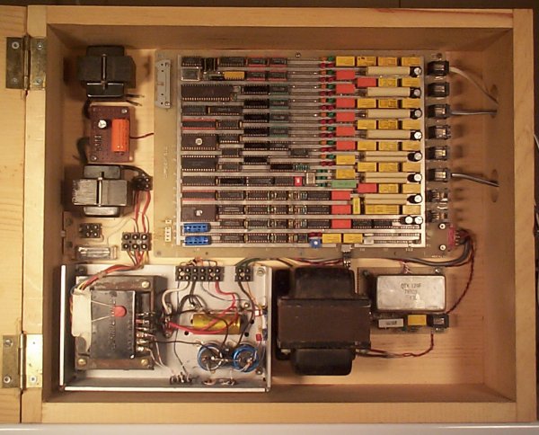
I did gain access to a lot of junked electronic components that would allow me to build complex projects. Also I had learned about microcontrollers which allow the construction of smart electronic projects. And lastly, I had begun to frequent suburban garage sales, where telephones of every description were plentiful and cheap. The stage was set to finally build my own dial telephone system. I spent several months of evenings and weekends on this, in the 1992-93 timeframe. I didn't draw a schematic for it, but I will give here what information I have in my notes or can remember.
This is intended for educational and/or entertainment purposes. In no way is it sufficient information to duplicate the circuit. Perhaps it will satisfy the next person who asks about it after reading the brag reference I inserted into this old Usenet posting.
| Dial Sequence | Function |
| Flash | Put current call on temporary hold, await command |
| 00 | Ring all stations |
| 01x | Set ring ring pattern: 0 --- --- 1 -- -- -- 2 - ---- 3 ---- - 4 ---- 5 - 6 - - 7 - - - 8 - - - - 9 ------ |
| 02 | Ring again -- redial last extension, if busy ring me back when it becomes free |
| 03x *x | Speed dial x (0-9) |
| 04x | Park/unpark call against extension x (put on hold so you can hang up / retrieve from hold.) |
| 05 | Park/unpark call against own extension |
| 06x | Forward calls to extension x, or to outside line with 069... |
| 060 | Cancel call forward |
| 081x... | Set speed dial x (0-9) with digits that follow |
| 082 | Disable/enable ringing for outside calls |
| 09 | Join incoming outside call in progress |
| 9 | Get outside line. If outside line already on hold, send a flash on it |
| # | Redial |
Extension 5 picks up the call. All phones stop ringing.
Extension 2 picks up too, gets dial tone. Wishes to join the incoming call, so dials 09. Connected to extension 5 and the outside line.
Extension 1 dials 9. Gets busy signal. Dials 02, gets stutter dialtone confirmation, hangs up.
Extensions 2 and 5 both hang up, terminating the outside call. Extension 1 gets a single short ring. Picks up the phone, is automatically connected to the outside line.
Extension 1 makes a pulse-dial call but the outside line is configured for DTMF so the PBX converts the digits.
Extension 1 parks the call by flashing, then dialing 05.
Extension 7 forwards all calls to an outside number by dialing 0697451576. Extension 3 retrieves the parked outside call by picking up and dialing 041.
Extension 8 dials 01800 to ring all available stations with the four-short-bursts ringing pattern. Prearranged signal for a certain person to pick up, whatever extension they are nearest. Extension 5 picks up, call is completed.
Extension 3 wishes to access a special feature on the outside line, transmits a flash by flashing to enter command mode (confirmed with stutter dial tone), dialing 9.
And so on...
The massively oversampled digital tone generator is because I am a digital weenie.
Similarly offhook detection in the line circuits could probably be done with solid-state circuitry but I actually like the chatter of the relays as phones are dialed.
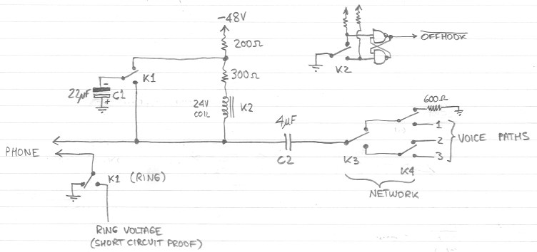
The voice paths 1-3 of all the line circuits are connected together. So if any given pair of line circuits select the same voice paths with relays K3 and K4, they can talk with each other. Any line that is not currently connected to a voice path is terminated via a 600 ohm resistor so that it doesn't sound funny.
When the phone goes offhook, current is drawn through the 200 and 300 ohm resistors and the line relay K2, which closes. Via the debounce circuit a clean OFFHOOK- signal goes to the control complex. Pulse dialing and switchhook flash are detected by timing the OFFHOOK- signal in software.
The large voltage changes caused by this are kept out of the voice circuitry by capacitor C2, which at 4uF is much larger than it needs to be.
To ring the line, ring voltage is generated and relay K1 is activated. This places capacitor C1 effectively in parallel with the relay coil, shunting the potentially strong ring current around it so that it doesn't chatter (which would result in "false trip", i.e. a false offhook indication.) However if the phone goes offhook, the capacitor is discharged by the DC current and the line relay closes within one or two cycles of the ring waveform. The control complex then immediately cuts off ringing by opening relay K1.
That's all there is to it, except for very careful sequencing of the relays. For example, the control signal to K1 is synchronized in hardware to the zero crossings of the ring waveform, and the voice path is connected via K3/K4 only when C2 is in steady state, so that no click results. For example, if the line has just picked up after being rung, a brief delay occurs before the call is connected.
Connected to each voice path is the circuitry to detect DTMF tones and generate audible call progress tones. I don't have a schematic for it, but I do have a wiring diagram which is just as good:
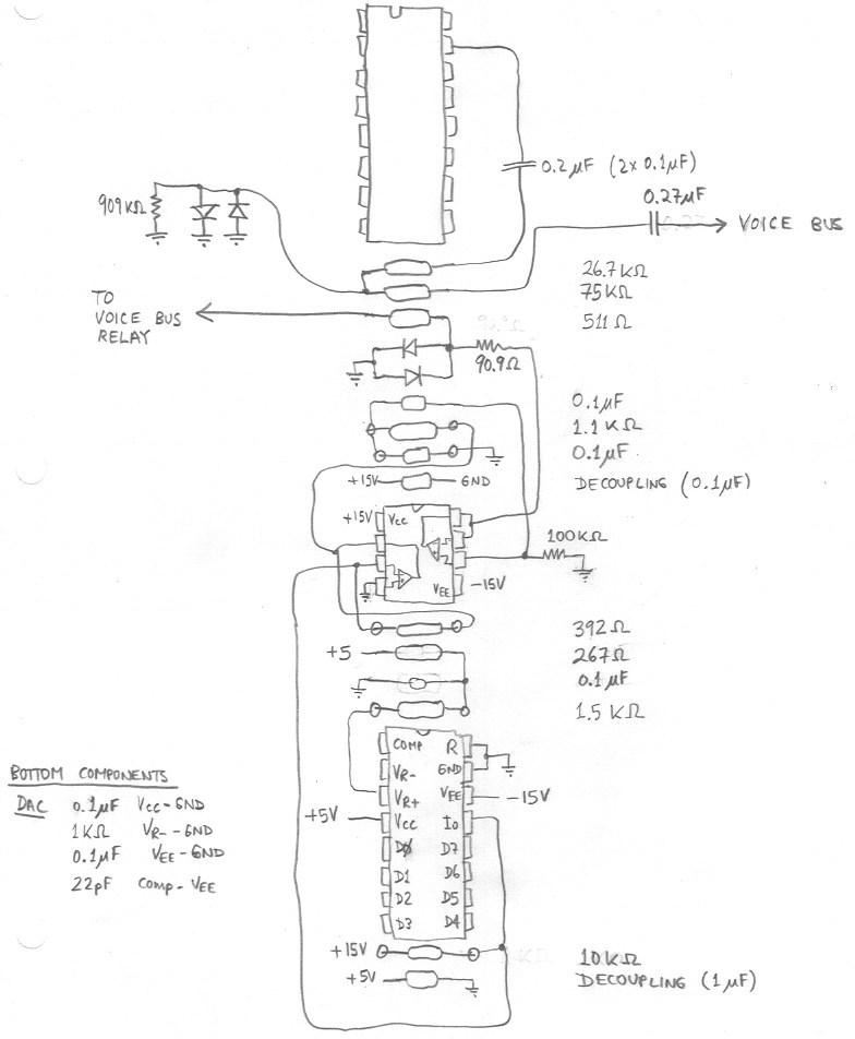
The top device is a Crystal Semiconductor 8870 DTMF receiver. It listens to the voice bus via a super conservative arrangement of resistors, capacitors and diodes to ensure it can't get damaged by voltage transients. Due to its high input impedance it can always listen.
The bottom device is a DAC-08 digital-to-analog converter for generating the tones. A dual op amp (LM358) is used to convert the current output of the DAC-08 to voltage, then rebuffer it after lowpass filtering. The output impedance is 600 ohms. Again, diode clamping is used to protect the electronics from harm. This circuit is only connected to the voice bus when needed via the voice bus relay (not shown) as the 600 ohm termination impedance is not wanted during an actual call.
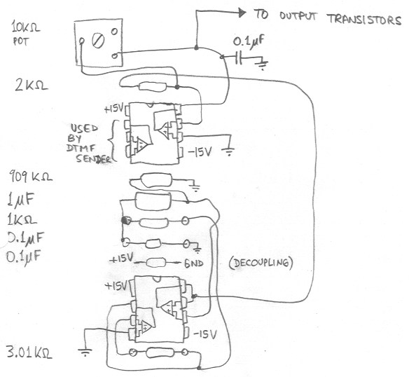
Next, here is the circuit that generates the ring waveform:
Not shown is the power supply which generates the following voltages:
The reason I don't show these things is not that they are more obvious than the other stuff, but that I don't have neat diagrams I can scan in.
    ns = 8640
    pi = 3.14159265#
    OPEN "tones.asm" FOR OUTPUT AS #1
    PRINT #1,"; Digitized ring, dial, audible ring, and busy tones"
    PRINT #1," .org 0"
    FOR i = 0 TO ns+3
       PRINT #1, " .byte ";
       PRINT #1, INT(SIN(2*i*2*pi/ns)*127.99+128);
       t1 = SIN(35*i*2*pi/ns)
       t2 = SIN(44*i*2*pi/ns)
       t3 = SIN(48*i*2*pi/ns)
       t4 = SIN(62*i*2*pi/ns)
       PRINT #1, ","; INT(t1*63.99+t2*63.99+128);
       PRINT #1, ","; INT(t2*63.99+t3*63.99+128);
       PRINT #1, ","; INT(t3*63.99+t4*63.99+128)
    NEXT
    CLOSE #1
The microprocessor controls all this with just seven control signals --
three 2-bit tone selects for the voice paths and a 1-bit ring voltage
enable. Digital sequencing automatically gates the tones on and off
at the 1/10 second points where they cross zero, so pulsed tones don't
have clicks where they are gated on and off. Likewise the ring voltage
is gated at zero crossing points, plus a synchronization signal is
generated somewhat ahead of the zero crossing point to allow the ring
relays to be switched close to it. All this makes the system "sound"
cleaner and also reduces wear & tear on the ring relay contacts.The ABEL files for the two PALs in the digital tone section can be found here and here.
| Address (hex) | Read | Write |
4000 4200 4400 4600 4800 6000 6400 6800 |
H8  H7  H6  H5  H4  H3  H2  H1


SW  V2  V1  V0  __DTMF rec 0__
                __DTMF rec 1__
                __DTMF rec 2__
| . . TN1 TN0 . D2 D1 D0 M8 M7 M6 M5 M4 M3 M2 M1 L8 L7 L6 L5 L4 L3 L2 L1 R8 R7 R6 R5 R4 R3 R2 R1 . RE _TS2__ _TS1__ _TS0__ . . . . _DTMF sender__ |
Where, for line x, Hx is the OFFHOOK input, Mx and Lx are the controls for relays K3 and K4 respectively, and Rx is the control for K1 (ring relay.) For voice channel y, Dy is controls the relay that connects the tone generator to the channel, "DTMF rec y" is the 4-bit DTMF receiver listening to the channel, Vy is DTMF tone valid for the channel, "TSy" is the call progress tone select for the channel (silence, dial, audible ring, busy.) RE is the ring voltage enable, "DTMF sender" is the control bits for the DTMF generator. TN1 and TN0 control the relays that connect the outside ("trunk") line to the one of the voice paths. SW is the DIP switch that selects pulse or tone dial for the central office line.
Not shown is the offhook control for the outside line, which is connected directly to P1.1 of the 8031, and the ring detect from the outside line, which is connected to P1.0.
The TSy and RE outputs are retimed in by the tone sequencing circuitry.
ULN2003 drivers are used for the relays.
The firmware was debugged by keeping a simple debug monitor and download program in ROM, and downloading the firmware to RAM for testing. No other debug tools were used. When the firmware was finished, it was burned into ROM. The serial port is not used with the final firmware.
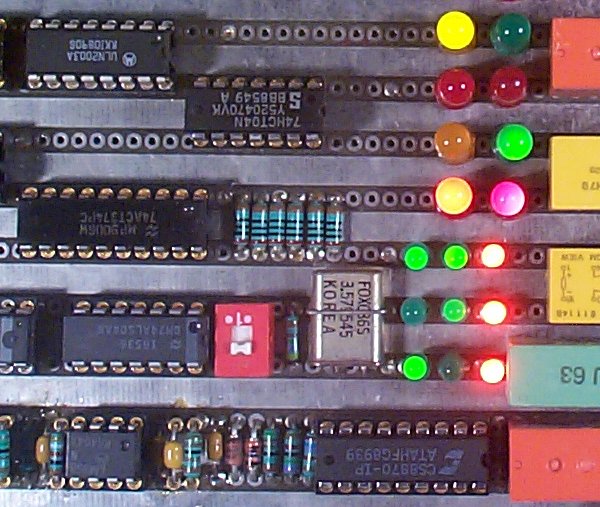 I wired a lot of LEDs into the circuit to show the status of all relays, the tone
selects, the ring voltage, the external ring detect. By picking up three phones
and dialing different extensions with different ring cadences, quite a neat
rhythm of clicks and flashing lights can be generated.
I wired a lot of LEDs into the circuit to show the status of all relays, the tone
selects, the ring voltage, the external ring detect. By picking up three phones
and dialing different extensions with different ring cadences, quite a neat
rhythm of clicks and flashing lights can be generated.
Despite the unbalanced lines, there don't seem to be hum pickup problems. I have had a telephone separated from the switch by about 100m of twisted-pair telephone wire and it worked fine.
The only value this thing has is entertainment value. It's great when there are guests with bored kids, and once set up it gets plenty of attention from the adults too, if they are engineers that is.
I don't actually use it for anything.
It was worth building because it finally scratched that childhood itch.